Adding
a 1G TCU to your 1G MT Harness
| There are a couple ways to add a TCU to
your M/T harness car. The easiest of course is just swapping
harnesses, but even that can get tricky due to some wiring
differences. When doing MT to AT conversion I prefer to just add the
AT wiring to the existing harness. There's 2 ways to do this:
Method 1: Take a AT harness and seperate the TCU wiring from the engine harness, so that it can be wired into your existing harness Method 2: Obtain the connectors off a AT car and build a harness For both methods, take note that AT wiring changed over the years, and you need to have the connectors for your year trans. 1G NT 2.0L AT wiring can be used for a turbo car with minor changes. (Have verified this with 3 plug style - have not looked into it with 1G 2 plug style yet, but I assume it is similar) For Method 1, you already have the transmission side
connectors wired into your TCU connectors for you. For Method 2,
you'll want to start out by matching up the wire colors between the TCU
plugs and the transmission plugs. Start cutting sections of wire to
connect the two sides. Make sure you use the proper gauge for each
wire. I usually make my harnesses approx. 3.5 feet. Once
you've connected all the wire colors from each side, there will be some
wires left over on the TCU plugs. Along with the power wire that you
will need to do some things with. Here is a chart that shows how
these wires interconnect, followed by descriptions of what to do with
each. |
||||||||||||||||||||||||||||||||||||||||||||||||||||||||||||||||||||||||||||||||||||||||||
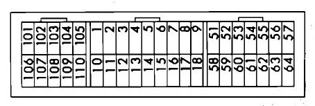
3 Plug TCU diagram:
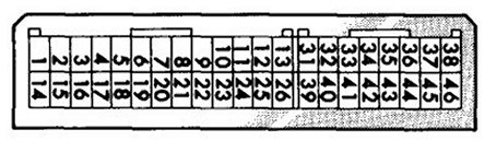
2 Plug TCU diagram:
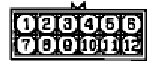
Ground - Connect all grounds to ground +12v Power - Tie these together and they will tap into a +12v ignition switched power off of the ECU, the same wires which power the ECU. One wire will split off this same power source to a pin on the 10 pin rotary switch connector. 3 Plug TCU type rotary switch - Pin 4 needs to be given +12v power from the same source as the TCU; pins 8 and 9 are not going to be used.
Power mode signal - wire this up either to an OEM switch or to any switch of your choice. +12v at this pin will put the TCU in power mode Tach signal - 91 to 94 will tie into OEM tach signal. Since 91-94 signal is inverted on a 1990, you will have to tap into the CAS wire on a 1990 harness Overdrive switch input - This works the same as the power switch. +12v at this pin enters overdrive mode. Wire it to OEM or your choice of switch Accelerator Switch - MT cars do not have this. However, there is a switch that does the same thing. The idle switch on the throttle body has the same logic. For an EMS car that does not use the idle switch, you can simply cut the OEM wire and use the idle switch for this. For an OEM ECU car, you will need to tap into this wire. This wire is not required if you don't want to bother with it. Diag. Output terminal - works like the ECU diag wiring; used for TCU diagnostic - not required, but can be wired up if you want diag stuff AC control relay - never bothered to look into how this works since most people don't run AC. It receives some sort of signal when AC is in use. Doesn't seem important even if you have AC. No need to deal with this. Diag. control terminal - used for TCU diagnostic - not required, but can be wired up if you want diag stuff Backup power source - this wires into the same backup power source that your ECU uses. Throttle position sensor - this ties into OEM TPS wire Vehicle Speed Sensor - ties into OEM VSS wiring Backup lights - Coming off of the rotary switch plug, there are two red wires, one with blue stripe + black dash, the other plain red + black dash. These are for the backup lights. Wire these two wires into the two wires that used to connect to the backup light switch on your manual transmission. Pins 10 and 11 are backup lights if you have this connector.
When using a set of plugs from an early (3 plug type) 2.0 NT in your early (3 plug TCU) Turbo car, you will need to move a wire in the TCU plug and obtain a 3 pin triangle plug. The NT harness has a 2 pin connector for the temperature senders where the early (3 plug) turbo models use a 3 pin connector with 2 temperature senders. The NT plug has a extra wire for lockup that the turbo cars do not have. You can remove this pin and move it to fill in the missing pin that is needed for the temperature sender. 3 plug pin 101 is the one not used, you can move it to pin (14 or 15, I can't remember which one is the missing one). Match up the wire colors to properly add the 3 pin triangle plug such that it matches up properly to the wiring on the transmission side. |